

D45A0 Rotary Buffer
Category:
Rotary buffer

Hotline:
- Detailed
-
model reverse torque Rotation direction Rotation direction D45A0-R503
5.0N.m
Clockwise damping 30kgf.cm
D45A0-L503
50±20kgf.cm
Anti-clockwise damping 30kgf.cm
D45A0-R703
7.0N.m
Clockwise damping 30kgf.cm
D45A0-L703
70±20kgf.cm
Anti-clockwise damping 30kgf.cm
D45A0-R104
10.0N.m
Clockwise damping 30kgf.cm
D45A0-L104
100±20kgf.cm
Anti-clockwise damping 30kgf.cm
Note: 1) The marked torque is the test data when the standard load falls slowly at 15° per second and the temperature is 23°C;
2) Special torque can be provided by changing the viscosity of the buffer grease.
use angle 180°
Operating temperature range -5~60℃
Material of product housing and cover Zinc aluminum alloy Rotary shaft material S25C
use oil silicone oil Dimensions
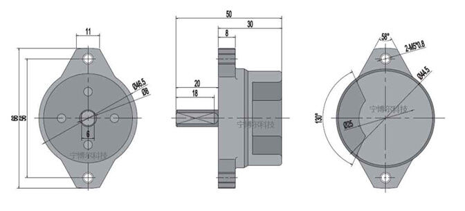
Instructions for use
1. When the D45 series rotary buffer starts to fall from the vertical position as shown in Figure A to the horizontal position, since the designed torque is weak at the starting position, with the rotation of the buffer angle, the torque gradually increases, so the action of the cover can be delayed. Close slowly. As shown in Figure B, when the cover starts to fall from the horizontal position, the torque generated by the gravity of the cover is zero in the vertical direction, and the torque is large at the rear position of the buffer, so the cover cannot be closed.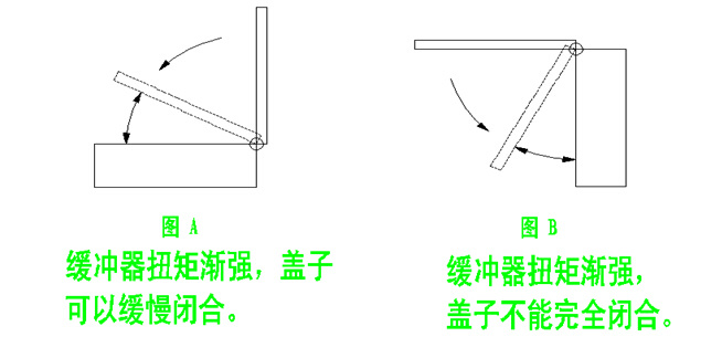
2. When using the rotary buffer in the example shown in the figure, please calculate the required torque according to the following calculation method.
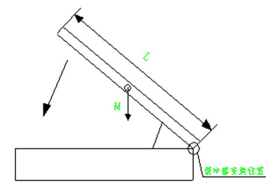
example:
Cover weight M: 5kg
The length L of the rotating shaft from the edge of the cover plate: 0.4m
Load torque: T=5×0.4×9.8÷2=9.8N•m
From the above calculation we choose the buffer as D45-104.
3. Please minimize the gap between the rotary shaft and the joint parts. If there is a gap, the speed of the cover plate will be affected when it is rotated and dropped.
4. The torque of the shock absorber also changes according to the change of the ambient temperature. The change rule is that when the ambient temperature increases, the torque decreases, and the action time is accelerated. When the ambient temperature decreases, the torque increases and the action time slows down. This is because the viscosity of the viscous oil also changes when the ambient temperature changes. But when the ambient temperature returns to normal temperature, the torque will also return to its original value.
5. The rotation angle of the buffer is 180 degrees. If the rotation exceeds 180 degrees, the buffer may be damaged. Please install a stop mechanism externally. The angle of action is based on the closed position.
 Keywords:
- rotary
- the
- of
- torque
- is
- when
- cover
- buffer
- temperature
- to
Key words:
相关产品

undefined
Messages
Service Line:
A701, Building 1, Hainengda Technology Factory, No. 3 Baolong Fourth Road, Baolong Community, Baolong Street, Longgang District, Shenzhen
0755-89253101


